
Walkman PLD
Walkman PLD
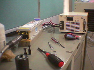
Fig. 1: The diode laser head with an attached fiber and the power supply.
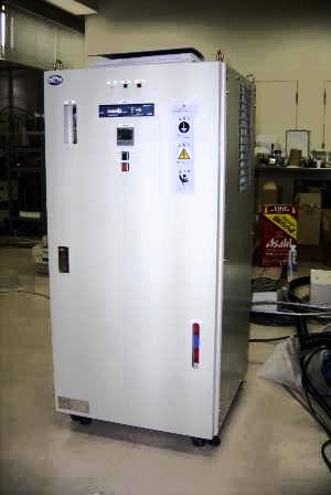
Fig. 2: The water cooler for the laser head.
A high-power diode laser is used for sample heating. This particular chamber used a 100 W cw laser. The laser light is delivered to the chamber through a fiber. The fiber connector is visible on the front of the laser head in Fig. 1. The power supply can deliver the 50 A max current required to drive the laser.
The laser head also produces a fair amount of heat, which must be removed with water cooling. Unfortunately we need deionized water, which also means that the cooler is quite large (Fig. 2). Indeed, much larger than the laser unit itself. Fortunately the cooler does not need to be close to the chamber, so this was not a major problem for fitting the whole system on the synchrotron beamline.
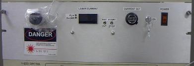
Fig. 3: Front panel of the heater unit. The optical fiber plugs into the connector on the left.
The cooler required a series of modifications to achieve proper interlocking for laser operation. If the cooling stops, the laser will likely self-destruct in a matter of milliseconds. The unit ensures that the flow rate is about 144 l/h, and the laser is automatically switched off if the flow drops below 120 l/h. Water temperature should be between 15 and 35°C, maximum conductivity is about 5 μS/cm, and the pressure should be between 3 to 6 bars.
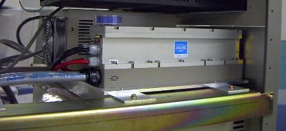
Fig. 4: The laser head mounted in the heater unit in the instrument rack.

Fig. 5: The top flange of the chamber
The laser head and power supply were mounted in the instrument rack. The optical fiber plugs into the front of the heater unit (Fig. 3). There are also manual controls for the laser head, although usually the laser is controlled by the computer and the manual controls are rarely needed.
The laser head itself (Fig. 4) is just behind the front panel. The power connections are kept as short as possible. The DI water lines are visible at the back of the laser head. A silica gel cartridge on top of the laser absorbs any moisture which may collect inside the laser housing.
The other end of the optical fiber plugs into the plug at the center of the top flange assembly (Fig. 5). There are three motorized rotation feedthroughs for sample and mask manipulation and the focusing optics is just above a viewport in the center. A simple two-lens focusing system is used. The lens position can be adjusted to change the heating area size for different types of experiment. The viewport is a simple pyrex unit with a suitable AR coating. The viewport itself does not get particularly hot even when the laser is operating at full power.