
SrTiO3 (001) etching
SrTiO3 (001) etching
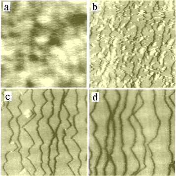
Fig. 1: AFM images of SrTiO3 substrates: (a) polished and BHF etched for (b) 5 min., (c) 8 min., (d) 12 min.1000 × 1000 nm2.
SrTiO3 substrates can be etched in NH4F-HF (buffered HF, BHF) at room temperature to obtain a Ti-terminated step-and-terrace surface. Buffering of HF is used to adjust the pH to around 3.7 to 4.3. Large numbers of etch pits appear if the pH is too low and residue remains on the surface if the pH is too high.[1, 2]
Before etching, the polished surface has fairly broad bumps with an average height of ~0.1 nm (Fig. 1a). The maximum height differences are on the order of 1.5 nm. BHF etching at room temperature for a few minutes starts to flatten the surface due tot he elatively high stability of the TiO2 layers. After etching for about 5 minutes, steps start to appear (Fig. 1b). From this point forward, etching proceeds in step-flow mode (Figs c and d). While the crystal etches mostly at the step edges, there is always the possibility of the acid etching a hole in a terrace. The delicate balance can be seen in Fig. 1c, where two partial etch pits of single unit cell depth have nucleated on two terraces.
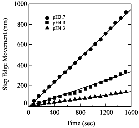
Fig. 2: Step edge etching rate for several pH values.
The pH of the etchant has to be adjusted so that the steps flow faster than the etch pits nucleate. Under these conditions, a clear step-and-terrace surface can be obtained without etch pits.
The etching rate, or step edge speed should be high enough to prevent etch pits from growing in depth. The easiest way to adjust the etching rate is to change the pH. For a more agressive etch, with pH around 3.7, the step flow rate can reach 1 nm/s. If the pH is increased to around 4, the step edge etch rate drops to around 0.1 nm/s. The etch rate also depends on the miscut direction, i.e. if steps are approximately parallel to the [110] direction, the etch rate is about 1.4 times faster than for steps that are parallel to the [100] or [010] directions.
The HF etching removes Sr more efficiently than Ti. It seems that the etchant mostly attacks the Sr at the step edges, dissolving it and then removing Ti by lift-off, as shown in Fig. 3.
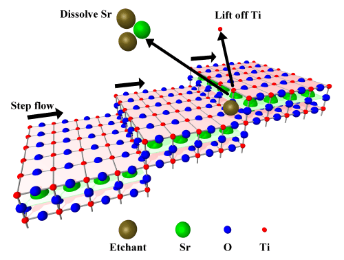
Fig. 3 Step-flow etching of SrTiO3, forming a step-and-terrace surface terminated by a perfect TiO2 layer.