
SrTiO3 (001) etching
SrTiO3 (001) etching
A real substrate is for all intents and purposes infinite in size, at least when dealing with atomic scale images and step edges. A simulated world, unfortunately, cannot be infinite, so special care must be taken when handling the unit cells which happen to be on the world edges.

Fig. 1: Possible edge cell configurations
The easiest solution is to ignore the problem by assuming that the world continues over the edge with the same pixel value (or unit cell height) as the pixel which the simulation is attempting to etch.
Fig. 1 shows what happens on the world edges. Obviously, no problems occur in the middle of a terrace. Questions arise when trying to etch a step edge/world edge site, such as those numbered 1 to 4 in Fig. 1. The easiest way is to assume that the next unit cell (across the edge) would have the same height as the edge site. Unfortunately this is not always a good choice. In positions 1 and 2 the choice is reasonable, but in positions 3 and 4 this choice is usually incorrect. How good or bad this model is depends on the angle at which step edges meet the world edges. In the following example the model works well.

Fig. 2: Initial state of SrTiO3 etch pit simulation for zero-angle miscut.
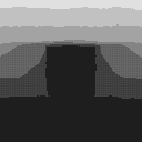
Fig. 3: Final state of SrTiO3 etch pit simulation for zero-angle miscut.
2x10⁸ steps, Probabilities p(0)=0, p(1)=0.01, p(2)=1, p(3)=1, p(4)=1
Quicktime movie
If the angle is different from 90 degrees, the simple edge model can lead to dramatic edge effects, which can, during a long simulation, become dominating! An example of such a case is shown below.
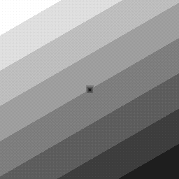
Fig. 4: Initial state of SrTiO3 etch pit simulation for random miscut direction.
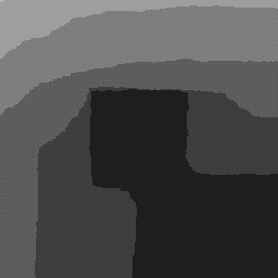
Fig. 5: Final state of SrTiO3 etch pit simulation for random miscut direction.
2x10⁸ steps, Probabilities p(0)=0, p(1)=0.01, p(2)=1, p(3)=1, p(4)=1
Quicktime movie